Firmware is customized for each type of transmission. This is due to the different control
solenoids and the operation of each Transmission. Below is an explanation of the different features,
although there is not much difference between the Classes. Some may only be available in the Advanced
class, depending on the difficulty of control.
Sensors
RPM and Speed sensors can be hall or magnetic type, or the unit could be tapped into existing
signals. TPS, Oil Temperature, Shifter Range Switch, Low Range Switch, Tune/Map Selection
Switch and Tiptronic Buttons can be used with this class.
Solenoids
This class can operate Multi Solenoids in a common positive and/or Common Negative connection.
It can do PWM and/or On/Off solenoids.
Speedo Calibration
The speedometer can be calibrated with this class.
Features
Features: Like 2nd Gear start, Drive/Overdrive Selection, Low Range calculation, Speedometer
Calibration and Oil Temperature Compensation can be done with this class.
Normal features are Tiptronic, 4 Tune/Map selections, Shift tuning per gear, and Line Pressure
Control, Lockup Control, etc.
GP Outputs
Up to 2 General outputs can be used for fan control, Shift light, etc.
Check out the technical data in the Overview / Features / Specifications / Product Comparison Chart below, or download the PDF version to check out the Mercury3 Product Information for guidelines on putting the right firmware, product, and drawings together.
Note: Documentation for TCU Compiling PDF is still in process. The products in this compiling tool are quite similar, so please ensure to read the supplied description documentation for the various products listed. Download PDF Compiling an ECU Product
Transmission Model Drawings
Getting started with Mercury3 and Hyperspace
Overview
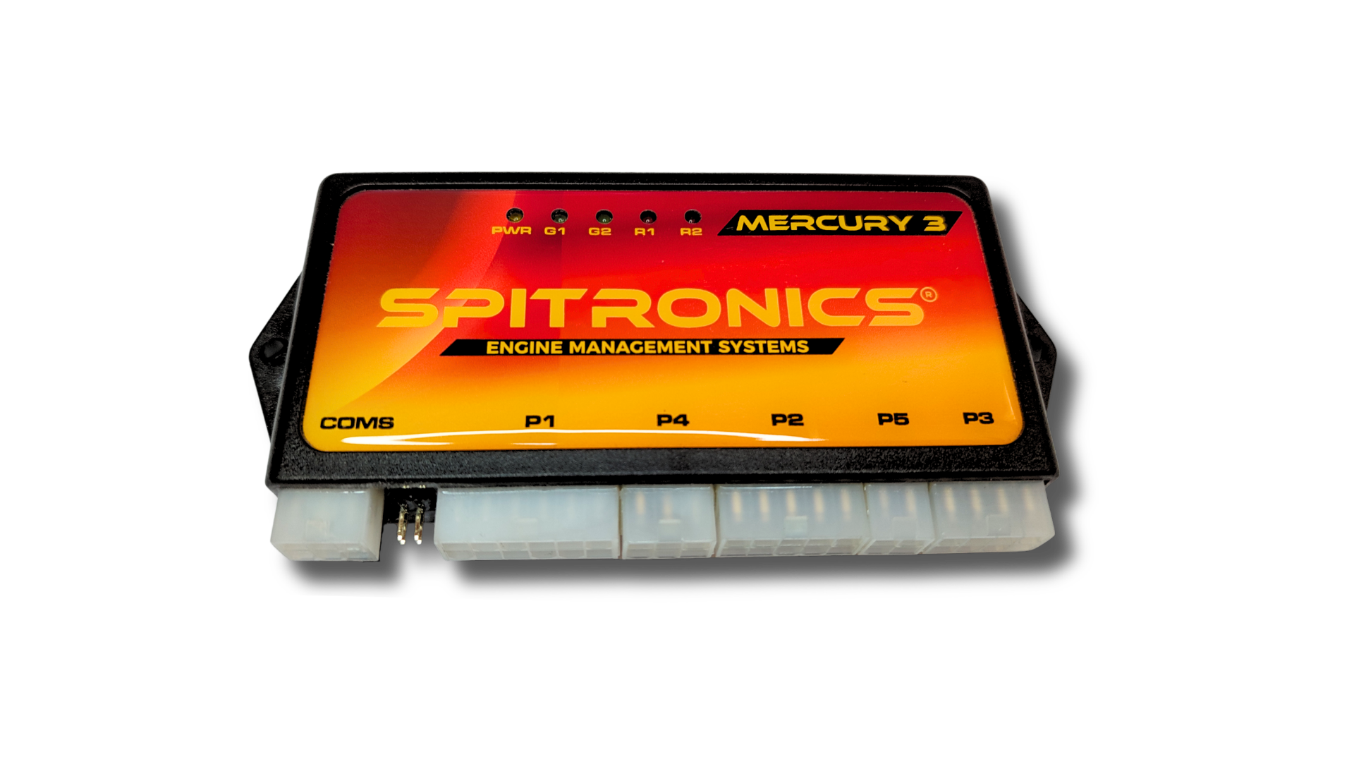
Spitronics Mercury3 has just been released. Now with Bootloader, no programmer needed! Upgrades to firmware from 3.6 to 3.7 with new software features to follow shortly as well as updates to this site regarding the product.
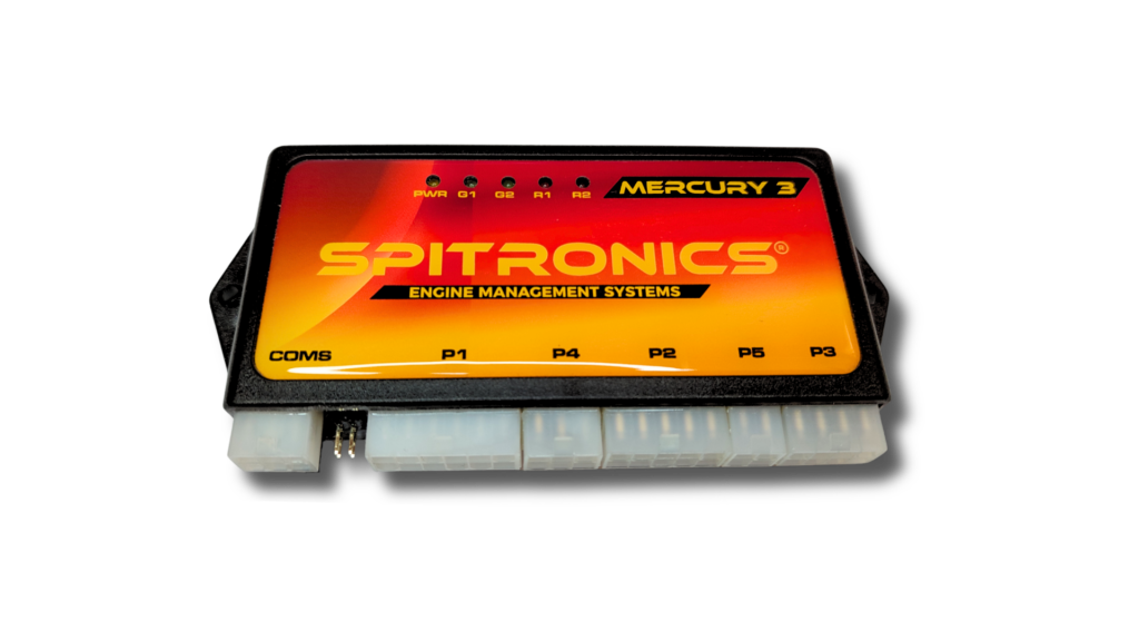
The MERCURY3 Control Unit is designed to be a cost effective replacement for high tech Engine Control Units (ECU) and Transmission Control Units (TCU). It uses unique and easy features which are easy to install and tune. It is designed with the novice and professional installer in mind.
This universal South African made product that can easily be customized for various engines or transmissions. It can be used for many applications such as racing engines, vehicle conversions, custom built vehicles, replacement parts for production vehicles etc. It is a compact reliable system which is epoxy filled to make it rugged and water tight for harsh environments and easy to mount in the driver’s compartment.
The Mercury3 unit is designed to connect directly to most sensors and drive units that is found on engines and transmissions. No need to modify them. It consist of the latest in high speed micro controllers with surface mount technology. These units are machine soldered to minimize human error.
The Mercury3 cover features like Lambda control, idle control, launch control, fuel pressure control, cam control, line pressure control, tiptronic gear control, stepper motor control and lots more. It has 8 positive drivers that can be converted to 12 coil igniter drivers for V12 engines. It has 8 negative injector drivers that can do full sequential injection for V8 engines and semi-sequential for V12 engines. 4 Negative drivers for GP outputs, rpm output, relay and electronic relay outputs. These drivers are ranging from 3.5 Amp to 6 Amp.
There are 9 analog input signals to measure water, air or oil temperature, throttle position, manifold pressure, lambda, fuel pressure, altitude etc. Then there are 4 trigger inputs to measure crank, cam & prop shaft angles.
The software is user-friendly and makes all the above features customizable by the tuner. This makes the Mercury3 adaptable for most engines and transmissions. Activations of features can be done over the internet making the unit viable to keep in stock and customize on demand.
This Mercury3 was designed to be universal and adaptable. Some firmware are customized to suit customers. New applications can easily be incorporated. Upgrades can be done over the internet.
To learn more about this amazing package browse through the features and specifications in the sub folders.
Features
Spitronics Mercury3 has just been released. Now with Bootloader, no programmer needed! Upgrades to firmware from 3.6 to 3.7 with new software features to follow shortly as well as updates to this site regarding the product.
Mercury3 ECU Features
Note: Some features may be in the development process in the near future. The hardware already has the capability for this development. Also note that not all of the features may be included on the same ECU as there is limited amount of drivers available. Some of the hardware classes may not include certain features due to the price range. See the selection chart for the ability of the different classes.
Fuel Delivery
· Accurate fuel amount and injection timing gives better performance and fuel consumption due to constant atomization on each cylinder.
· Injection methods such as Batch, Split Batch, Split Sequential and Full Sequential are offered with the Mercury3.
· Different Tuning options such as graph or matrix can be selected.
· All graphs or matrix data are interpolated to smooth fuel calculation accuracy for the best performance though the operating ranges.
· Fuel is calculated with MAP or TPS sensor signals versus RPM or a combination of the two. This will accommodate most engines ranging from street to racing and from economy to performance.
· Other sensors that are used to alter the fuel mixture are Water, Air, Altitude, Lambda, Battery Volts, Fuel Pressure and throttle response from the driver.
· Fuel injection timing is adjustable on gear type crank angle sensors as low as 12 pulses per revolution. This will result in a 30° angle resolution or smaller.
· Adjustable MAP sensor, reading angle for multiple throttle body systems.
· Dual injectors can be used in two methods. Staged injectors namely Ratio adjust or Graph Fazed method.
· Fuel pressure control can be done with pressure compensation maps.
· Injector trimming up to 8 injectors can be used for Full Sequential Injection.
· Fuel enrichment can be adjusted during Launch, RapidFire or retard functions.
Ignition Spark & Timing
· The Mercury3 can manage Distributors, Wasted Spark coil packs, Wasted Spark COP coils or Full Sequential spark systems.
· Mercury3 uses standard automotive coil packs found on engines. No need to change them.
· Most Smart Coils with built in drivers can be connected directly.
· Basic Coils is connected via the Mercury Coil drivers that is sold separately in different versions. Coil drivers can be stacked to accommodate V12 systems and V8 Dual Coil engines. The latter have 16 coils.
· The Mercury3 high performance firing module ensure a high quality spark adequate to ignite most mixtures of different fuels. It also has built in protection against overload conditions.
· Mercury3 has very accurate ignition timing especially with the gear type triggers.
· Timing is calculated with MAP or TPS sensor signals versus RPM or a combination of the two. This will accommodate most engines ranging from street to racing.
· Other sensors that is used to alter the Ignition Timing is Water, Air and Altitude.
· Battery Volts is used to compensate for coil charge time.
Sensors
· Mercury3 can use most standard sensors on the engine – No need to do modifications on distributors or converter boards.
· Custom Bolt-On Timing Gears may be used for older engines that run carburetors or engines with incorrect setups. Gear type triggers do make timing more accurate and responsive during blip conditions. This is the preferred method for racing applications.
· Sensors can be calibrated to accommodate the different types found on the engines.
Idle Control & Cold Start – This functions will ease with starting a cold engine and keep the RPM’s constant when air conditioners or automatic transmissions draw power from the engine. Idle control is included on board for one and two wire idle valves. The Spitronics stepper control units can be connected to control quad and bipolar stepper motors.
Launch Control – This feature will increase boost pressure during pull-off to eliminate Turbo Lag. Various methods are available to activate launch like buttons clutch switches TPS position etc. It can also do delayed launch recovery to improve traction.
Anti-Lag Control – This feature will increase boost pressure during racing to eliminate Turbo Lag on corners. Newer firmware has an output option to activate EGR valves to bypass turbo pressure to the exhaust. This will help with engine braking in corners and to keep boost pressure high for accelerating out of the corner.
Flat-shift Control – This feature will momentarily cut engine power during wide open throttle to assist in manual gear shifting.
RapidFire – This launch feature will make a machine gun sound in the exhaust which is desired by the drifting crowd. The frequency is adjustable and the amount of flames displayed at the outlet.
General Purpose Outputs – Up to 10 GP drivers can be used if there are enough available. They can be used for injectors, fan control, shift light, Aircon Cut-Out on Pull-Off or Up-Hill etc.
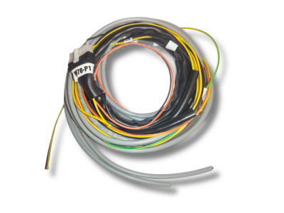
Standard Harness – No need to keep several harnesses in stock for different engines. Level 2 harnesses will include relays and fuses that will ease installation and save time. All the input wiring harnesses use screened cables for neatness of installation and to prevent electromagnetic interference which may cause erratic behavior of the ECU.
Compact Electronics – This will make the ECU easy to install under the dashboard as it takes very little space.
Complete Firmware for Most Engines.
Cost Effective – No need to buy expensive systems as all the necessary features are included with the ECU.
Rotary Systems – The 2 & 3 rotor engines are covered by this Mercury2. 4 & 6 Rotors can be done as well.
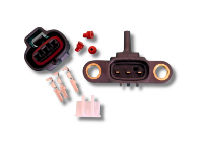
External Map Sensor – Easy to change between 1Bar, 2.5Bar, 3Bar 4Bar & custom configurations. External sensors are used to reduce the delay in the vacuum signal It makes the ECU more versatile to adapt to standard MAP sensors found on engines.
Altitude Compensation – This feature is important as the ECU will automatically compensate for differences in pressure.
Fuel Pressure control – This will control the speed of the fuel pump which eliminate the need for the mechanical fuel pressure regulator and return fuel line. It also compensates injector time versus fuel pressure to ensure accurate mixtures during blip conditions.
Standard Tuning Software – All the products use the same software. The features that is not used or allowed in the firmware will be blanked out.
Easy DIY Instructions – Save money on installation if you are a person who is up to the challenge.
Start-Up Maps included – This will make for easy start-up & tuning with the help of a Lambda sensor.
User Friendly Tuning Software which is extensively explained in the manual.
Tuning map can be locked to prevent tampering. Useful for engine builders who gives guarantees.
No Dyno Required – Tune your own vehicle with the help of the data logger in the software and save money. Just following the instructions in the manual carefully.
(Note that the last five points are for the person who is handy with tools and understand wiring and operation of an engine. If you are not sure, download the software, Map, manual and drawing and experiment with it first. It’s free of charge!)
Specifications
Power Supply
12V Ignition power 200mA, filtered by reverse polarity Diode, 700mA Poly switch and 25V Tranzorb
12V Relay power 14A Max, filtered by reverse polarity Diode
2.5mm2 Earth Strap
Inputs
4x Trigger inputs – Magnetic Isolated (2 Inputs require a 1K pull-up resistor for Hall or Optic inputs)
5x Analogue input 0 – 5V
1x 2K NTC Temperature Sensor Input
1x 10K NTC Temperature Sensor Input
1x Lambda Input 0 – 1 V or Processed 0 – 5V signal.
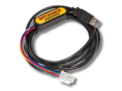
Software UART Connection via USB2 converter cable
Firmware Programmer Connection
Outputs
8x 6A P Channel Mossfets 12V output Floating, Over-current protected
8x 6A N Channel Mossfets Ground output Floating, Over-current protected
1x Mechanical Relay 3.5A Ground Output Floating, Over-current protected
1x RPM 3.5A Ground Output Floating with 1K pull-up resistor to 12V, Over-current protected
2x General Purpose 3.5A Ground Output Floating, Over-current protected
5V 600mA Power Output for TPS & Map Sensor
Electronic Relay 5V 5mA output for Spitronics custom 45A solid state relay
Dimensions
Size 145mm x 68mm x 21mm
Weight 240g
4 x Connector Type Plastic Molex 12, 10, 8, 6
1 x Comms Connector Type Plastic Molex 6
Load Sites ECU
| Tuning Pallet | load sites | Resolution | Adjustment | Adjustment | |
| | | Resolution | Range | |
| Fuel Vacuum Graph | 64 | Auto Range | 0.1 ms | 0 to 25 ms | Interpolated |
| 5 x Fuel RPM Graph | 32 | Auto Range | 1% | -50% to 50% | |
| Micro Fuel Vacuum Graph | 32 | Auto Range | 0.1 ms | 0 to 25 ms | Interpolated |
| | | | | |
| Dynamic Timing Graph | 150 | 100 RPM | 1° | 0° to 45° | Interpolated |
| 2 x Vacuum Timing Graph | 32 | Auto Range | 1° | -15° to 25° | Interpolated |
| Trailing Degrees Graph | 30 | 500 RPM | 1° | 0° to 45° | Interpolated |
| | | | | |
| Water Temperature Timing Graph | 18 | -40° to 140° | 1° | -50° to 100° | Interpolated |
| Water Temperature Fuel Graph | 18 | -40° to 140° | 1% | -50% to 100% | Interpolated |
| | | | | |
| Air Temperature Timing Graph | 18 | -40° to 140° | 1° | -50° to 100° | Interpolated |
| Air Temperature Fuel Graph | 18 | -40° to 140° | 1% | -50% to 100% | Interpolated |
| | | | | |
| Lambda MAP Graph | 24 | Auto Range | 1% | -50% to 50% | Interpolated |
| Lambda RPM Graph | 24 | Auto Range | 1% | -50% to 50% | Interpolated |
| | | | | |
| Injection Degrees Graph * | 30 | Firmware | Firmware | 0° to 720° | Interpolated |
| | | | | |
| TPS Fuel Graph | 20 | 0% to 100% | 1% | -50% to 50% | Interpolated |
| | | | | |
| Fuel Matrix | 16×16 | Auto Range | 0.1 ms | 0 to 25 ms | Interpolated |
| Timing Matrix | 16×16 | Auto Range | 1° | 0° to 45° | Interpolated |
| Cam1 Matrix * | 8×8 | Firmware | Firmware | Firmware | Interpolated |
| Cam1 Matrix * | 8×8 | Firmware | Firmware | Firmware | Interpolated |
| | | | | |
| Fuel Pressure Set point Graph | 12 | Auto Range | 0.1 Bar | 0 to 7 Bar | Interpolated |
| Fuel Pressure Correction Graph | 30 | Auto Range | 1% | -50% to 50% | Interpolated |
| | | | | |
| Battery Fuel Graph | 20 | 0.5V | 1% | -50% to 50% | Interpolated |
| Battery Charge Time Graph | 20 | 0.5V | 1% | -50% to 50% | Interpolated |
* Not yet implemented
Load Sites TCU
| Tuning Pallet | load sites | Resolution | Adjustment | Adjustment | |
| | | Resolution | Range | |
| 8x Gear Profiles Upshift | 3 | Auto Range | 1% | 0 to 100% | Interpolated |
| 8x Gear Profiles Downshift | 3 | Auto Range | 1% | 0 to 100% | Interpolated |
| 8x Gear Profiles Lockup | 2 | Auto Range | 1% | 0 to 100% | Interpolated |
| | | | | |
| 3 x Duty Control Graph | 50 | 100 % TPS | 1% | 0 to 100% | Interpolated |
| 2 x Oil Temperature Graph | 15 | -40° to 140° | 1% | -50% to 50% | Interpolated |
| | | | | |
Product Comparison Chart
The Mercury3 is sold in six hardware classes categorized by the features required for each engine or transmission. The advantage is that basic applications is sold cheaper than more complex applications. These features can be activated or changed over the internet which eliminates time lost and courier costs. This makes it viable to have these units in stock at low entry cost and activate the features later when the project is started. The PC Tuning software is standard for all units. Certain features will be blanked out if it is not available. The firmware categories are Micro, Basic, Standard, Intermediate, Advance and Ultimate. On the ECU only 4 classes are implemented at this stage and on the TCU only 1 class. Please look at the following charts to see which hardware class will suit your application.
ECU Selection Chart
| Mercury3 Hardware | Standard | Intermediate | Advance | Ultimate | |
| | | | | |
| Hardware Inputs | | | | | |
| Map Sensor | 1 | 1 | 1 | 1 | |
| TPS Sensor | 1 | 1 | 1 | 1 | |
| Water Temp Sensor 2K NTC | 1 | 1 | 1 | 1 | |
| Air Temp Sensor 10K NTC | 1 | 1 | 1 | 1 | |
| Lambda | 1 | 1 | 1 | 1 | |
| Altitude Sensor | 1 | 1 | 1 | 1 | |
| Built In Altitude Sensor | | | | | |
| Tuning Pot | 1 | 1 | 1 | 1 | |
| Fuel Pressure Sensor | | | 1 | 1 | |
| Dual Map Switch | | | | | |
| Battery Volts | 1 | 1 | 1 | 1 | |
| Power Management | 1 | 1 | 1 | 1 | |
| | | | | |
| Crank Trigger Pulse | 1 | 1 | 1 | 1 | |
| TDC/Home Pulse | 1 | 1 | 1 | 1 | |
| VVTI Cam 1 Pulse | | | | 1 | Note 1 |
| VVTI Cam 2 Pulse | | | | 1 | Note 1 |
| USB/Programmer 9Pin D-Sub | 1 | 1 | 1 | 1 | |
| USB/Programmer 6Pin Molex | | | | | |
| | | | | |
| Hardware Outputs | | | | | |
| Injector Drivers Negative Out | 2 | 8 | 8 | 8 | |
| Internal Coil Drivers Negative Out | | | | | |
| External Coil Triggers Positive Out | 1 | 1 | 8 | 8 | |
| RPM Output | 1 | 1 | 1 | 1 | |
| Electronic Relay Output | 1 | 1 | 1 | 1 | |
| Relay Output | 1 | 1 | 1 | 1 | |
| GP Outputs | 2 | 2 | 2 | 2 | |
| | | | | |
| Features | | | | | |
| Graph Tuning | 1 | 1 | 1 | 1 | |
| Matrix Tuning | 1 | 1 | 1 | 1 | |
| Idle Control | 1 | 1 | 1 | 1 | Note 2 |
| Dual Maps | 1 | 1 | 1 | 1 | |
| Micro Fueling or Fazed Injector | 1 | 1 | 1 | 1 | |
| Full Sequential Injector Control | | 1 | 1 | 1 | |
| Fuel Pressure Control | | | 1 | 1 | |
| V-Tech Cam Control | 1 | 1 | 1 | 1 | |
| VVTI Cam Control | | | | X | |
| Launch control | 1 | 1 | 1 | 1 | |
| Anti-Lag control | X | X | X | X | |
| Flat-Shift control | X | X | X | X | |
| Boost control | | | | X | |
| Throttle x Wire control | | | | X | |
| RPM Calibration | 1 | 1 | 1 | 1 | |
| | | | | |
| Epoxy filed | 1 | 1 | 1 | 1 | |
| Can be Epoxy filed | | | | | |
| | | | | |
| Notes | | | | | |
| Note 1 – Only magnetic sensors – Requires external Pull-up Resistor for Hall or |
| Optic Sensors. Cam 2 input may be used for Dual Map selection. | |
| Note 2 – For Stepper motors external hardware is required | | | |
| X – Capable – Firmware not yet developed | | | | |
TCU Selection Chart
| Mercury3 Hardware | Intermediate | Notes |
| | |
| Hardware | | |
| TPS Sensor | 1 | |
| RPM Sensor | 1 | Note 1 |
| Speed Sensor | 1 | Note 1 |
| Oil Temp Sensor | 1 | |
| Low Range Sensor | 1 | |
| | |
| Shifter Selection Switch | 1 | |
| Tuning Maps Selection Switch | 1 | |
| Tiptronic Up Switch | 1 | |
| Tiptronic Down Switch | 1 | |
| | |
| GP Outputs | 2 | |
| | |
| Solenoid Drivers Negative Out | 8 | Note 3 |
| Solenoid Drivers Positive Out | 8 | |
| Speedo Output | 1 | |
| Electronic Relay Output | 1 | |
| Relay Output | 1 | |
| Battery Volts | 1 | |
| | |
| Features | | |
| Tiptronic Function | 1 | |
| Quad Tuning Maps | 1 | |
| Individual Gear Profiles | 1 | |
| Duty Cycle Control | 1 | |
| Speedo Calibration | 1 | |
| Lockup Control | 1 | |
| Lockup Selectable / Gear | 1 | |
| Transfer Box Ratio Adjustments | 1 | |
| Number of Gears Capable | 8 | |
| Power Management | 1 | Note 5 |
| Epoxy filed | 1 | |
| Can be Epoxy filed | | |
| | |
| Notes | | |
| Note 1 – Only magnetic sensors directly – Requires an external Pull-up Resistor for Hall or Optic Sensors. |
| Note 3 – 2 drivers is used for Lockup and Function display LED’s |
| Note 5 – Hardware can keep itself powered after Ignition Off |